It’s probably been a while since you’ve dealt with your computer’s motherboard. You don’t have to, as long as you simply sit at your PC or notebook and carry out everyday tasks.
However, if you want to replace a component such as the graphics card or SSD with an upgrade, it is highly recommended that you research the existing internal connections and their cabling on the circuit board. This preparatory work will save you trouble later on: You decide from the outset in favor of the right component that fits mechanically and at the same time can actually achieve its maximum performance.
In the case of SSDs and graphics cards, you will immediately come across the SATA and PCI Express interfaces. Although SATA is considered outdated technology, it is still important for updating hard drives, especially in many older notebooks.
Further reading: The best SSDs of 2024
The opposite is true for PCIe: The interface is so powerful that it has not only successfully succeeded SATA, but is also available in different versions and connector formats. It is precisely this versatility that can cause confusion, but with a little connection know-how, you don’t have to worry about it in the first place.
SATA: Long the standard connection for drives
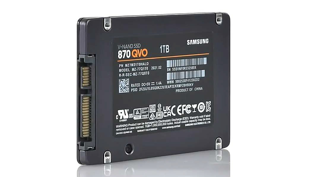
In addition to 3.5-inch magnetic hard drives, SSDs in 2.5-inch format still rely on the SATA 600 interface. These flash drives are now available in capacities of up to 8TB.
IDG
Serial ATA, or S-ATA (abbreviated SATA): The “Serial Advanced Technology Attachment” interface has long been the standard for mass storage and removable storage drives such as CDs and DVDs.
Nowadays, it is widely used for magnetic hard drives and SSDs in 2.5-inch format as well as for the M.2 slot. In the case of SSDs, it is becoming less and less popular and is being replaced by PCI Express. HDDs continue to rely on the SATA interface.
The current version is SATA 6G, which is also known as SATA-III or SATA-600. This is the third generation of the SATA specification with a theoretical transfer rate of 600MB/s, from which the designation SATA-600 is derived.
In practice with SATA SSDs, sequential data transfers of over 500MB/s in writing and around 550MB/s in reading are possible. SATA 6G is backwards compatible. However, the previous versions SATA-I and -II are probably only rarely still in use.
eSATA: The SATA interface for external hard drives
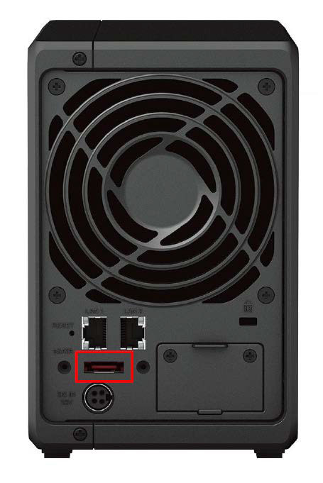
The eSATA connection is an external SATA interface for external storage solutions. It is now only rarely found — for example on NAS enclosures such as this one from Synology.
IDG
The external SATA connection, or eSATA for short, leads the internal interface to the outside in order to connect an external drive. It does not require additional components such as USB. eSATA works at the same transfer rate as SATA. However, the external interface requires special cables and connectors.
In addition, no power can be transmitted via eSATA. The mobile drive must therefore usually be supplied with power via a separate power supply unit. The lack of a power supply is particularly impractical for use with notebooks.
For this reason, a combination socket is often used here, which combines eSATA with USB in one connection. The connected eSATA device receives power via the USB part. Data is transferred via the eSATA part.
These connections are no longer found on notebook housings. USB has replaced them thanks to its versatility. However, eSATA ports are still occasionally used on network storage devices (NAS) to connect an external hard drive.
SATAe: Successor connection that failed to establish itself
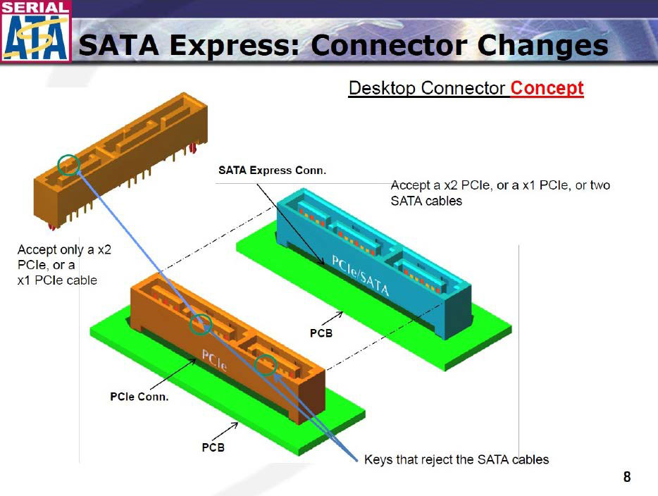
The SATA Express SSD connection was the first to use PCIe for transfer, but was also intended to be used with SATA hard disks. However, it never caught on — partly because of PCI Express.
IDG
SATAe, or SATA Express, was intended as the successor to SATA 6G, but did not catch on.
The idea was to use PCI Express instead of SATA for the physical transfer of SSDs. By bundling two SATA ports and transferring them via PCI Express, the previous SATA 6G speed was to be doubled. This creates a PCIe x2 connection. With PCIe 2.0 this corresponds to 1,000MB/s, with PCIe 3.0 2,000MB/s.
In order to keep SATAe downwards compatible, the connector has a three-part design. Two SATA hard drives can be connected to the connector. The transfer speed then falls back to SATA. In addition to the two SATA sockets, it has an area for the PCIe clock signals and the power supply.
However, corresponding flash drives have never become established. The main reason for this is the limitation to two PCIe lanes. For comparison: M.2 SSD drives utilize up to four PCIe lanes. With PCIe 3.0, they achieve almost 4,000MB/s.
PCIe: Universal interface for many computer components
The Peripheral Component Interconnect Express interface — PCI Express or PCIe for short — connects the components directly to the processor and/or the I/O hub. The abbreviation PCIe is always coupled with a number that indicates the generation and therefore the theoretical maximum transfer speed.
As a serial transfer method, PCIe uses so-called lanes, which can be bundled to increase the data transfer rate. The higher the PCIe version number, the higher the transfer speed per lane.
The number of lanes required for ideal control depends on the respective component. This is indicated by the number after the letter “x,” which also characterizes the different slot sizes on the mainboard — such as x1, x4, x8, or x16. An x1 slot is very short, while an x16 slot is comparatively long.
Further reading: The best graphics cards for gaming
PCIe transfer speed: This is a combination of the PCIe version and the number of lanes. For example, with PCIe 3.0, the rate per lane is 8GT/s (gigatransfers per second). This corresponds to a bandwidth of 970MB/s per lane. With PCIe 3.0 x4, 3.9GB/s are theoretically possible.
However, the practically usable data rate is lower. The reason: In addition to pure data transfer, transfer protocols also utilize the bandwidth.
PEG slot – the extra slot for the graphics card
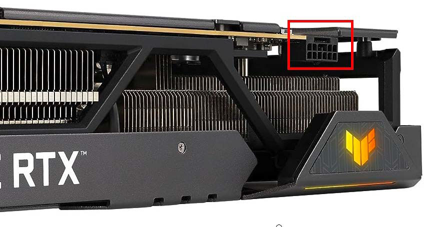
Power-hungry graphics cards, such as the Asus TUF GeForce RTX 4090 shown here, require more power than the PCIe x16 slot can provide. Extra power connections can now have up to 12 pins and provide several hundred watts extra — with a correspondingly powerful power supply unit.
IDG
PEG stands for PCI Express for Graphics and describes a slot on the mainboard that is intended for the graphics card. It is equipped with up to 16 PCIe lanes and can provide a maximum of 75 watts of power. In contrast, other PCIe slots are limited to a maximum of 25 or even just 10 watts.
As the power supply via the slot alone is often not sufficient for a graphics card, the power supply to the GPU can be increased via an additional connection to the power supply unit. A 6-pin connector provides a further 75 watts, while a 6- to 8-pin cable provides a maximum additional 150 watts.
In the case of high-performance graphics cards for gamers, several 8-pin cables may also be required to cover the power requirements.
Nvidia is a good example of how power-hungry current GPUs are. Since the Geforce RTX 3000 series, the manufacturer has opted for a 12-pin power connection, which can be designed for up to 600 watts of additional power.
The technical data for the graphics card provides information on which power connectors are compatible. The cables are usually included with the power supply unit. In rare cases, the graphics card manufacturer also supplies suitable cables. A correspondingly powerful power supply unit is a mandatory requirement.
Flexible but confusing: PCIe slots and lane allocation
PCI Express turns out to be very flexible in practice. For example, each generation is backwards compatible. You can therefore also operate a PCIe 4.0 graphics card on a PCIe 3.0 mainboard.
However, the data transfer performance falls back to the lower speed of the host system. At the same time, a PCIe 1.0 card can also be used in a computer with a higher PCI Express version. However, it will not work any faster as a result.
What’s more, you can even use the slots flexibly. For example, an x1 card will also work in an x4 slot. However, the mainboard architecture must be taken into account. This is because not every slot is automatically wired with full lanes.
For example, if there are two PEG slots, one of which is occupied by a graphics card, it will be supplied with 16 lanes. This means that there are no lanes left for the second slot.
However, it is also possible for eight lanes to be automatically switched to the second slot as soon as a card is inserted there. This also applies if the card does not require this number of lanes. The wiring is so varied that only a study of the mainboard manual will provide information on how it works in individual cases.
PCIe via M.2 slot for compact solid state discs (SSDs)
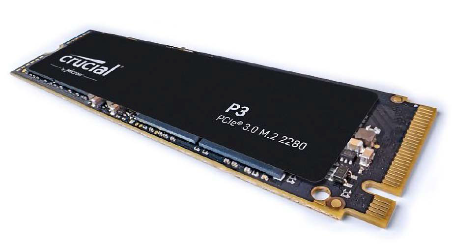
The 2280 format is widely used for SSDs for the M.2 slot. In many cases, you can read the size and PCIe version directly from the product designation — as with this Crucial SSD from the P3 series.
IDG
M.2 is an interface specification that emerged from the Next Generation Form Factor (NGFF). The compact socket allows particularly small modules to be connected via PCIe with up to four lanes.
As this easily overcomes the limiting factor of SATA in terms of transfer speed, M.2 has quickly become established for internal SSDs — for example in particularly flat notebooks (ultrabooks).
The slot determines the size of the M.2 SSD. On most mainboards, you will find M.2 with the identifier 2280. It stands for 22 millimetres wide and 80 millimetres long. This specification is important as it not only determines the size of the appropriate card, but also the position of the fastening screw. Other sizes are 2230, 2242, or 22110, which only differ in length.
SSDs for the M.2 slot utilize the NVMe transfer protocol (Non-Volatile Memory Express), which uses PCIe for transfer. This is why they are also referred to as NVMe SSDs. To be able to boot from an M.2 SSD, the computer requires an NVMe driver in the BIOS. This is now the case almost without exception. NVMe drivers are also integrated into all common operating systems.
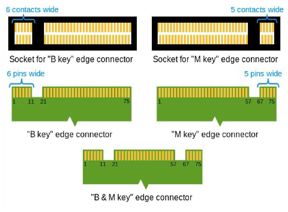
So-called keys ensure that a card can be operated in the respective M.2 slot. The B, M, or B+M slots are commonly used for internal SSDs.
IDG
Special features of M.2 SSDs: The M.2 slot is not only reserved for SSDs with a PCIe controller. There are also combination slots that can accommodate and control SATA SSDs. As soon as the M.2 slot is occupied by a SATA SSD, it switches from PCIe to SATA.
The speed advantage of PCIe is thus lost. Even pure SATA M.2 slots can still be found on older notebook boards or in housings for external SSDs.
You can recognize which M.2 SSD is present by the cut-outs on the connection of the module, which are known as “keys.” They ensure that only compatible cards can be inserted in the slot. M.2 SSDs for PCIe (x2 and x4) can be recognized by a cut-out — Key M. Variants with two cut-outs on the right and left (Keys B+M) usually only support PCIe x2 or SATA.
This article was translated from German to English and originally appeared on pcwelt.de.
Graphics Cards, Storage
However, if you want to replace a component such as the graphics card or SSD with an upgrade, it is highly recommended that you research the existing internal connections and their cabling on the circuit board. This preparatory work will save you trouble later on: You decide from the outset in favor of the right component that fits mechanically and at the same time can actually achieve its maximum performance.
In the case of SSDs and graphics cards, you will immediately come across the SATA and PCI Express interfaces. Although SATA is considered outdated technology, it is still important for updating hard drives, especially in many older notebooks.
Further reading: The best SSDs of 2024
The opposite is true for PCIe: The interface is so powerful that it has not only successfully succeeded SATA, but is also available in different versions and connector formats. It is precisely this versatility that can cause confusion, but with a little connection know-how, you don’t have to worry about it in the first place.
SATA: Long the standard connection for drives
In addition to 3.5-inch magnetic hard drives, SSDs in 2.5-inch format still rely on the SATA 600 interface. These flash drives are now available in capacities of up to 8TB.
IDG
Serial ATA, or S-ATA (abbreviated SATA): The “Serial Advanced Technology Attachment” interface has long been the standard for mass storage and removable storage drives such as CDs and DVDs.
Nowadays, it is widely used for magnetic hard drives and SSDs in 2.5-inch format as well as for the M.2 slot. In the case of SSDs, it is becoming less and less popular and is being replaced by PCI Express. HDDs continue to rely on the SATA interface.
The current version is SATA 6G, which is also known as SATA-III or SATA-600. This is the third generation of the SATA specification with a theoretical transfer rate of 600MB/s, from which the designation SATA-600 is derived.
In practice with SATA SSDs, sequential data transfers of over 500MB/s in writing and around 550MB/s in reading are possible. SATA 6G is backwards compatible. However, the previous versions SATA-I and -II are probably only rarely still in use.
eSATA: The SATA interface for external hard drives
The eSATA connection is an external SATA interface for external storage solutions. It is now only rarely found — for example on NAS enclosures such as this one from Synology.
IDG
The external SATA connection, or eSATA for short, leads the internal interface to the outside in order to connect an external drive. It does not require additional components such as USB. eSATA works at the same transfer rate as SATA. However, the external interface requires special cables and connectors.
In addition, no power can be transmitted via eSATA. The mobile drive must therefore usually be supplied with power via a separate power supply unit. The lack of a power supply is particularly impractical for use with notebooks.
For this reason, a combination socket is often used here, which combines eSATA with USB in one connection. The connected eSATA device receives power via the USB part. Data is transferred via the eSATA part.
These connections are no longer found on notebook housings. USB has replaced them thanks to its versatility. However, eSATA ports are still occasionally used on network storage devices (NAS) to connect an external hard drive.
SATAe: Successor connection that failed to establish itself
The SATA Express SSD connection was the first to use PCIe for transfer, but was also intended to be used with SATA hard disks. However, it never caught on — partly because of PCI Express.
IDG
SATAe, or SATA Express, was intended as the successor to SATA 6G, but did not catch on.
The idea was to use PCI Express instead of SATA for the physical transfer of SSDs. By bundling two SATA ports and transferring them via PCI Express, the previous SATA 6G speed was to be doubled. This creates a PCIe x2 connection. With PCIe 2.0 this corresponds to 1,000MB/s, with PCIe 3.0 2,000MB/s.
In order to keep SATAe downwards compatible, the connector has a three-part design. Two SATA hard drives can be connected to the connector. The transfer speed then falls back to SATA. In addition to the two SATA sockets, it has an area for the PCIe clock signals and the power supply.
However, corresponding flash drives have never become established. The main reason for this is the limitation to two PCIe lanes. For comparison: M.2 SSD drives utilize up to four PCIe lanes. With PCIe 3.0, they achieve almost 4,000MB/s.
PCIe: Universal interface for many computer components
The Peripheral Component Interconnect Express interface — PCI Express or PCIe for short — connects the components directly to the processor and/or the I/O hub. The abbreviation PCIe is always coupled with a number that indicates the generation and therefore the theoretical maximum transfer speed.
As a serial transfer method, PCIe uses so-called lanes, which can be bundled to increase the data transfer rate. The higher the PCIe version number, the higher the transfer speed per lane.
The number of lanes required for ideal control depends on the respective component. This is indicated by the number after the letter “x,” which also characterizes the different slot sizes on the mainboard — such as x1, x4, x8, or x16. An x1 slot is very short, while an x16 slot is comparatively long.
Further reading: The best graphics cards for gaming
PCIe transfer speed: This is a combination of the PCIe version and the number of lanes. For example, with PCIe 3.0, the rate per lane is 8GT/s (gigatransfers per second). This corresponds to a bandwidth of 970MB/s per lane. With PCIe 3.0 x4, 3.9GB/s are theoretically possible.
However, the practically usable data rate is lower. The reason: In addition to pure data transfer, transfer protocols also utilize the bandwidth.
PEG slot – the extra slot for the graphics card
Power-hungry graphics cards, such as the Asus TUF GeForce RTX 4090 shown here, require more power than the PCIe x16 slot can provide. Extra power connections can now have up to 12 pins and provide several hundred watts extra — with a correspondingly powerful power supply unit.
IDG
PEG stands for PCI Express for Graphics and describes a slot on the mainboard that is intended for the graphics card. It is equipped with up to 16 PCIe lanes and can provide a maximum of 75 watts of power. In contrast, other PCIe slots are limited to a maximum of 25 or even just 10 watts.
As the power supply via the slot alone is often not sufficient for a graphics card, the power supply to the GPU can be increased via an additional connection to the power supply unit. A 6-pin connector provides a further 75 watts, while a 6- to 8-pin cable provides a maximum additional 150 watts.
In the case of high-performance graphics cards for gamers, several 8-pin cables may also be required to cover the power requirements.
Nvidia is a good example of how power-hungry current GPUs are. Since the Geforce RTX 3000 series, the manufacturer has opted for a 12-pin power connection, which can be designed for up to 600 watts of additional power.
The technical data for the graphics card provides information on which power connectors are compatible. The cables are usually included with the power supply unit. In rare cases, the graphics card manufacturer also supplies suitable cables. A correspondingly powerful power supply unit is a mandatory requirement.
Flexible but confusing: PCIe slots and lane allocation
PCI Express turns out to be very flexible in practice. For example, each generation is backwards compatible. You can therefore also operate a PCIe 4.0 graphics card on a PCIe 3.0 mainboard.
However, the data transfer performance falls back to the lower speed of the host system. At the same time, a PCIe 1.0 card can also be used in a computer with a higher PCI Express version. However, it will not work any faster as a result.
What’s more, you can even use the slots flexibly. For example, an x1 card will also work in an x4 slot. However, the mainboard architecture must be taken into account. This is because not every slot is automatically wired with full lanes.
For example, if there are two PEG slots, one of which is occupied by a graphics card, it will be supplied with 16 lanes. This means that there are no lanes left for the second slot.
However, it is also possible for eight lanes to be automatically switched to the second slot as soon as a card is inserted there. This also applies if the card does not require this number of lanes. The wiring is so varied that only a study of the mainboard manual will provide information on how it works in individual cases.
PCIe via M.2 slot for compact solid state discs (SSDs)
The 2280 format is widely used for SSDs for the M.2 slot. In many cases, you can read the size and PCIe version directly from the product designation — as with this Crucial SSD from the P3 series.
IDG
M.2 is an interface specification that emerged from the Next Generation Form Factor (NGFF). The compact socket allows particularly small modules to be connected via PCIe with up to four lanes.
As this easily overcomes the limiting factor of SATA in terms of transfer speed, M.2 has quickly become established for internal SSDs — for example in particularly flat notebooks (ultrabooks).
The slot determines the size of the M.2 SSD. On most mainboards, you will find M.2 with the identifier 2280. It stands for 22 millimetres wide and 80 millimetres long. This specification is important as it not only determines the size of the appropriate card, but also the position of the fastening screw. Other sizes are 2230, 2242, or 22110, which only differ in length.
SSDs for the M.2 slot utilize the NVMe transfer protocol (Non-Volatile Memory Express), which uses PCIe for transfer. This is why they are also referred to as NVMe SSDs. To be able to boot from an M.2 SSD, the computer requires an NVMe driver in the BIOS. This is now the case almost without exception. NVMe drivers are also integrated into all common operating systems.
So-called keys ensure that a card can be operated in the respective M.2 slot. The B, M, or B+M slots are commonly used for internal SSDs.
IDG
Special features of M.2 SSDs: The M.2 slot is not only reserved for SSDs with a PCIe controller. There are also combination slots that can accommodate and control SATA SSDs. As soon as the M.2 slot is occupied by a SATA SSD, it switches from PCIe to SATA.
The speed advantage of PCIe is thus lost. Even pure SATA M.2 slots can still be found on older notebook boards or in housings for external SSDs.
You can recognize which M.2 SSD is present by the cut-outs on the connection of the module, which are known as “keys.” They ensure that only compatible cards can be inserted in the slot. M.2 SSDs for PCIe (x2 and x4) can be recognized by a cut-out — Key M. Variants with two cut-outs on the right and left (Keys B+M) usually only support PCIe x2 or SATA.
This article was translated from German to English and originally appeared on pcwelt.de.
Graphics Cards, Storage